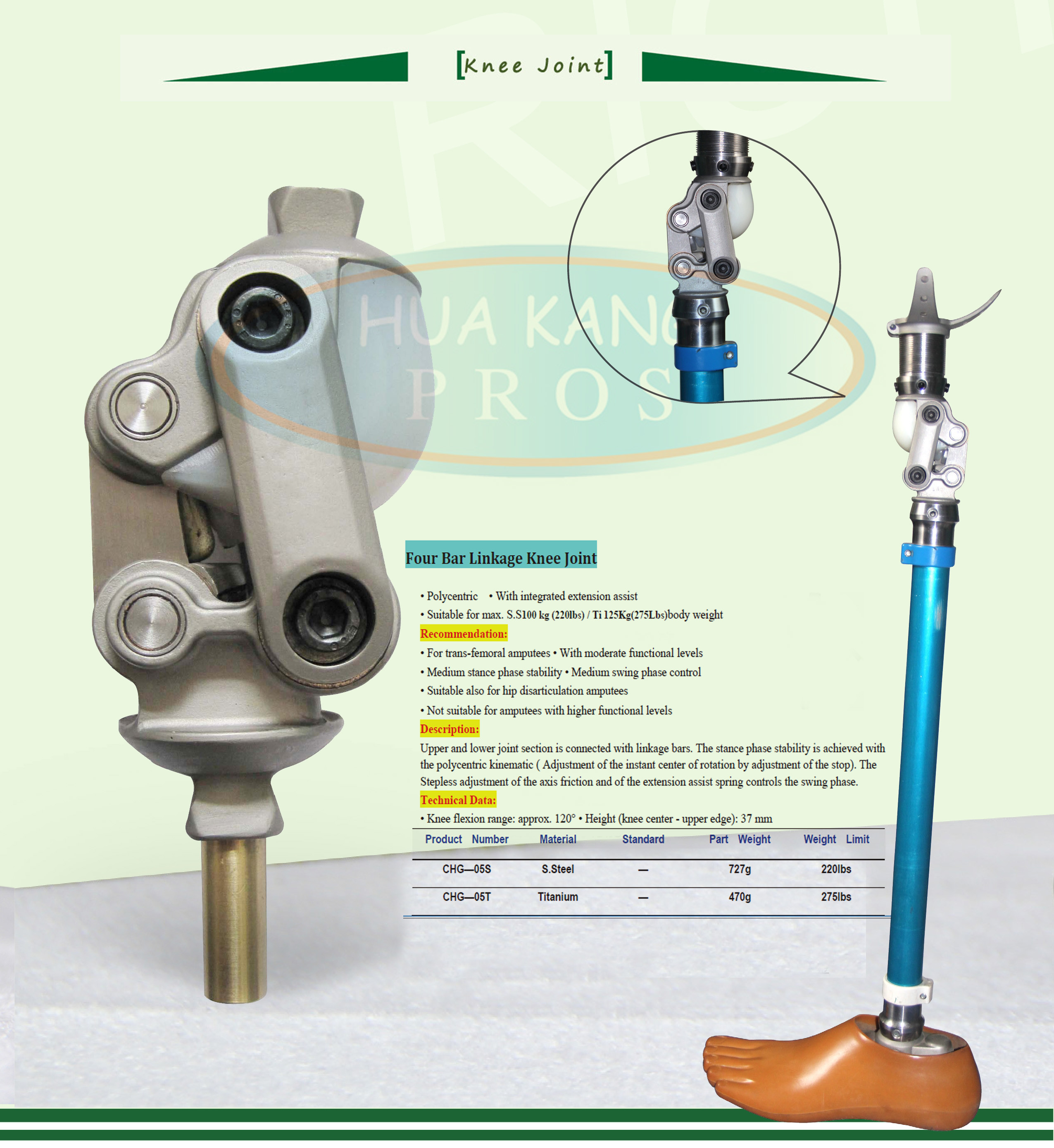
Polycentric
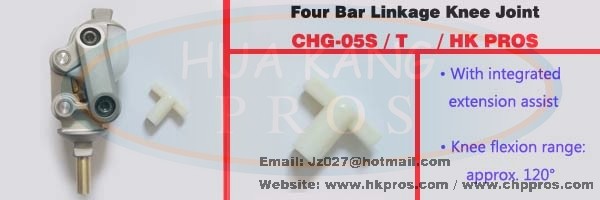
• with integrated extension assist
• suitable for max. 100 kg body weight
Recommendation:
• for trans-femoral amputees
• with moderate functional levels
• medium stance phase stability
• medium swing phase control
• suitable also for hip disarticulation amputees
• not suitable for amputees with higher functional levels
Description:
Upper and lower joint section is connected with linkage bars. The stance phase stability is
achieved with the polycentric kinematic ( adjustment of the instant center of rotation by
adjustment of the stop). The stepless adjustment of the axis friction and of the extension
assist spring controls the swing phase.
Technical Data:
• Knee flexion range: approx. 120°
• Height (knee center - upper edge): 37 mm
|
Product Number
|
Material
|
Standard
|
Part Weight
|
Weight Limit
|
|
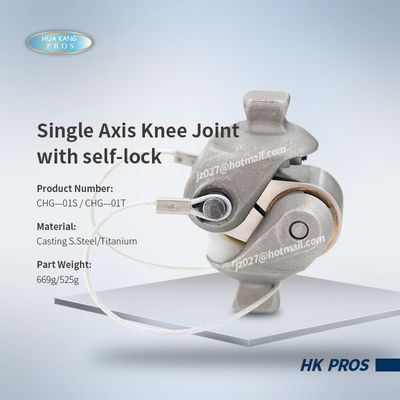
CHG—05S
|
S.Steel
|
—
|
727g
|
220lbs
|
|
CHG—05T
|
Titanium
|
—
|
470g
|
220lbs
|
Manual
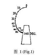
1.Description and Function
The Four Bar Linkage Knee Joints CHG-05S/CHG-05T are polycentric knee joints. The center of rotation changes its position, dependent on the degree of flexion (Fig.1). The joint provides a rotational and translational movement due to its polycentric action. So the joint close to the real characteristics of the knee of people. People who fit this kind of knee can get well walking. In the extended position the instantaneous center of rotation is located above the joint and posterior to the weight bearing line, thus providing knee stability in the stance phase (see Section 3). During flexion the center of rotation decline sharply with flexion and back to the usual position of knee axis so that patient can kick easily and without appearance problem when sitting.

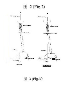
2.Alignment
The staring point for correct alignment is the determination of the individual weight bearing line and transfer of these values to the components in the prosthesis according to the illustrated alignment recommendations (Fig.2). Function of the joint is influenced by the position of the axes.Thus when providing basic alignment, the two lower axes should create a horizontal line from the lateral aspect
3.AdjustingStance Phase (Fig.3)
Turn the Adjustment Screw and vary the position of the center of rotation according to the individual requirements of the patient. Put the center of rotation forward make flexion easier but decrease stability. Inversely, put the center of rotation backward increase stability but make flexion harder. Use a 4mm hex head wrench.Clockwise rotation=decrease stability of the joint (initiation of flexion becomes easier). Counter–clockwise rotation = increase stability (initiation of flexion becomes harder).
4.Setting Swing Phase Speed with Axis Friction Adjustment (Fig.4)
Setting swing phase speed by adjusts the axis friction (resistance to motion) using enclosed wrench, and turn cap screw using a 5mm hex head wrench. Clockwise rotation = increase friction = decrease Swing Phase Speed. Counter-clcokwise rotation = decrease friction = increase Swing Phase Speed Adjustments of as little as 5° to 10° provide a preceptible change.
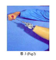
5.Regulating the Swing Phase with Extension Assit Adjustment(Fig.5)
Adjust the tension of the spring for Extension Assist by turning the Adjustment Screw.Use a 4mm hex head wrench. Clockwise rotation Clockwise rotation = increase the tension of the spring = increase Swing Speed. Counter-clcokwise rotation = decrease the tension of the spring = decrease Swing Speed. Adjust the tension of the spring need in concert with axis friction adjustment depth of the adjustment screw in the spring housing should not exceed 8mm.
6.Technical Data
Structure height 37mm(from axis center to upper edge)
Overall height 108mm(form pyramid to pyramid)
Maximum flexion angle 120°
Weight CHG-05S/ CHG-05T 727g/ 470g
7.Maintenance
- After the knee has been worn for a few weeks, readjusments may need to be provided. It is recommended that patient be seen in this time frame to make any necessary corrections.
- After the knee has been worn for long time, if Knee Axis bushing has heace serious frazzle and impossible recover the original function, it can be sent back to producer and change new one, if without serious frazzle, please apply lubricant to the axis pins in the cone shaped bushings(you’d better use lubricant supplied by producer).When you remove the Anterior Linkage bar, please remember the original position of it, Apply Lubricant after cleaning the Anterior Linkage Bar and Knee Axis Bushing by coal oil or gasoline. Recommend applies lubricant annually.

 Your message must be between 20-3,000 characters!